
2024-2025
5-DOF robotic arm for MARIA, the Robocol rover
A five-degree-of-freedom robotic arm for the Robocol rover: lead-screw linear rail, cycloidal reducers at the shoulder and elbow, differential wrist and interchangeable grippers. I designed it as mechanical lead.
- Mechanical design
- CAD
- FEA simulation
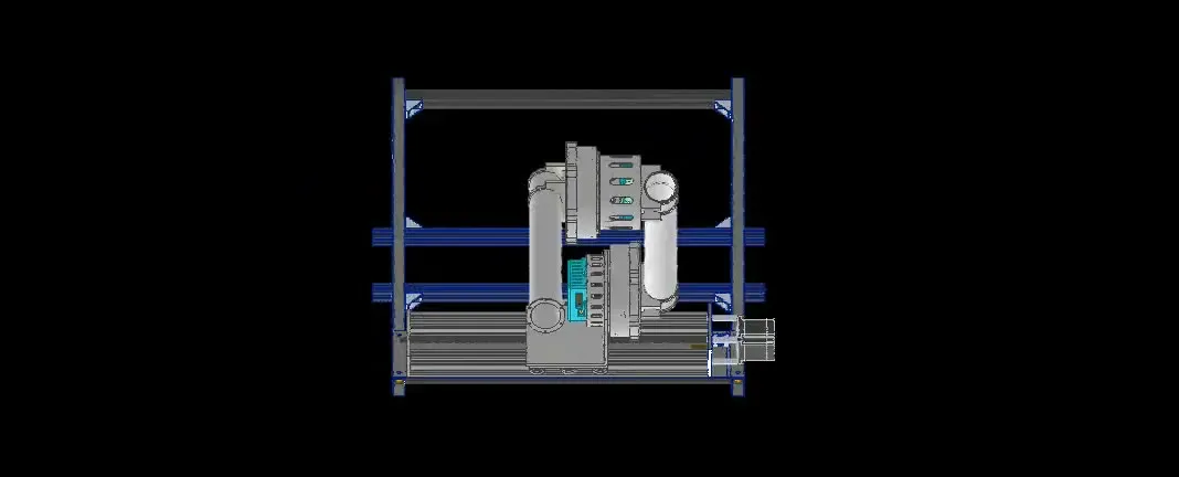
As Robocol’s mechanical lead, I led the design of the robotic arm for MARIA, the new rover, from requirements definition to detailed CAD in Autodesk Inventor. My time at Robocol ended before the arm was fully built; this page documents the design. The arm had to perform fine manipulation, such as flipping switches or inserting a USB drive, and also lift loads, in the University Rover Challenge’s servicing and delivery missions.
Requirements
| Requirement | Value |
|---|---|
| Payload | 5 kg |
| Reach | 1 m in the XZ plane, 1.5 m in Y |
| Precision | < 2.25 mm |
| Mass | < 12 kg |
| Simplicity | 4–5 degrees of freedom, minimum part count and quick assembly |
Concept generation and selection
I organized the arm team by function (base, links, joints, wrist, gripper and control) and led a research and brainstorming phase with competitor analysis. Each concept was documented with its source, advantages, drawbacks and risks, and scored against the four design criteria (reliability, precision, lightness and simplicity) using an analytic hierarchy process (AHP) and decision matrices.
Architecture
- Structure: carbon fiber tube links, for their stiffness-to-weight ratio.
- DOF 1, linear rail: the arm travels on a 6061 aluminum rail driven by a lead screw with a NEMA 23 motor, adding a translational axis and avoiding repositioning the rover for each task.
- DOF 2 and 3, shoulder and elbow: two custom cycloidal reducers, 40:1 at the shoulder (more torque to move the whole arm) and 30:1 at the elbow (more speed for end-effector precision), driven by brushless motors with ODrive controllers. Housings and most internal parts are high-strength aluminum, with a 1020 steel crankshaft.
- DOF 4 and 5, differential wrist: worm gears and stepper motors, 3D-printed.
- End effector: two interchangeable grippers, an underactuated cable-driven one for precision tasks and a force gripper with a rigid finger for a firm grip.
CAD render of the arm, December 2024.
Reducer validation
The cycloidal reducers were first designed and checked in Inventor, then 3D-printed as a proof of concept with the brushless motor and ODrive, to evaluate torque transmission, backlash and efficiency under load before machining them in aluminum. We applied DFMA and geometric dimensioning and tolerancing (GD&T) to the links and reducers.
Finite element analysis also changed how the arm was mounted: modeling the rails integrated into the chassis (200 N and 80 N·m) showed they deformed the aluminum extrusions, so the rails were moved onto a plate. The analysis is in Finite element analysis applied to design decisions.
Before MARIA: the 6-DOF arm
In the previous stage, for the 2024 University Rover Challenge, Robocol competed with a six-degree-of-freedom arm. I did not design it: my contribution was the arm’s CAD modeling and support with the models for the rover simulation in Gazebo. That experience was the basis for setting the requirements of the new arm.
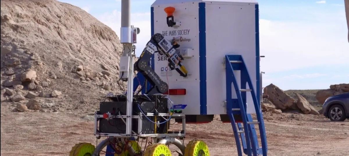 The 6-DOF arm at URC 2024.
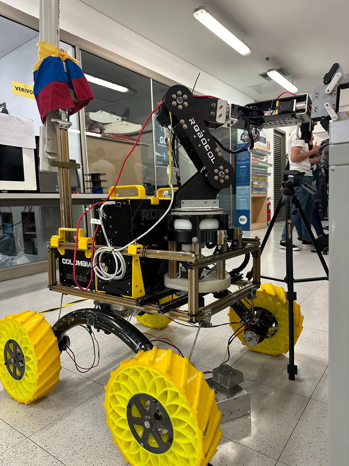 The 6-DOF arm mounted on the previous rover.
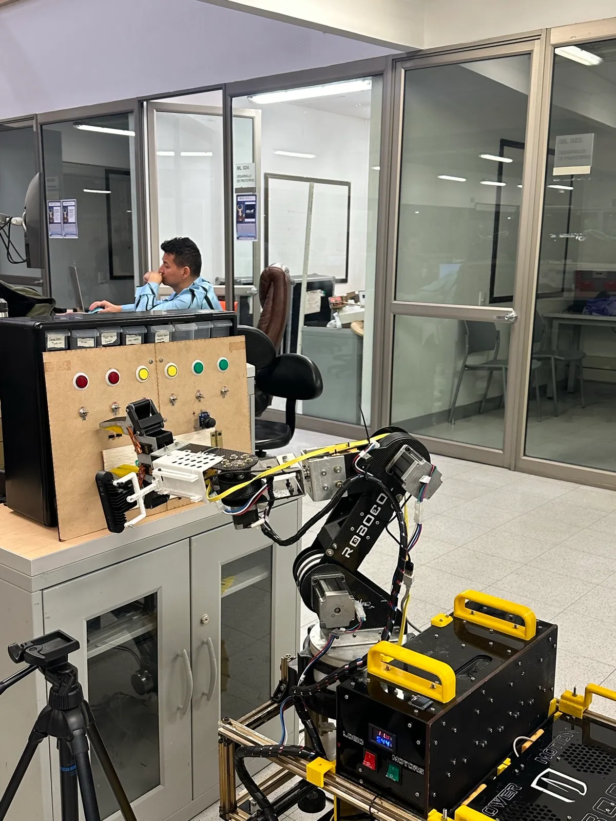 Lab testing, in front of the servicing panel.
6-DOF arm test routine: flipping a lever.
6-DOF arm test routine: inserting a USB drive.
The full story, including the management of the new rover, is in the Robocol chapter.