
2025
Redesign of a thread bonding machine for Leader-Indumar
Engineering consulting for a Colombian textile company. We redesigned its bonding line to go from 6 to 18 simultaneous threads; I was in charge of the detailed design of the new winder.
- Mechanical design
- CAD
- Project management
Client and problem
Leader-Indumar is a Colombian company that makes technical threads. After twisting the thread, they bond it: they dip it in a polyurethane solution, cure it in an oven and wind it onto cones. The polymer layer binds the fibers, prevents fraying and protects the thread from friction and wear.
Their bonding machine processed 6 threads at a time. They needed at least 15, ideally 18, to reach a total speed of 200 m/min, without buying a new machine and without taking up more floor space.
It was an 18-week consulting project of the Uniandes Mechanical Engineering Consulting Office, in a team of five students advised by professors Daniel Serrano and Jonathan Camargo.
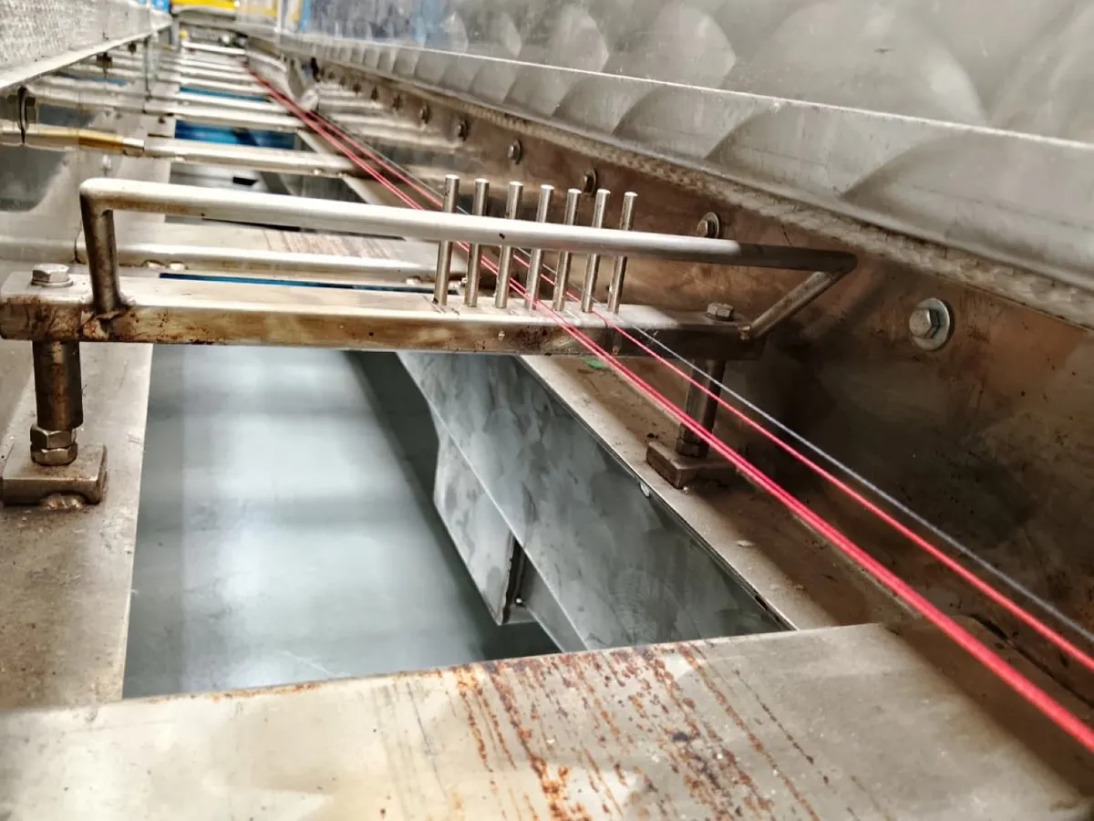 Threads running through the original machine, at the plant.
Requirements
- Capacity: from 6 to at least 15 threads, with 18 as the target.
- Spacing: enough distance between threads so the adhesive doesn’t stick them together, especially inside the oven.
- Break detection: one counterweight sensor per thread (18 in total) that stops the machine if a thread breaks.
- Standardization: an operating matrix relating gauge, speed and temperature for uniform bonding.
- Ergonomics and space: at most 300 × 50 cm of floor space, and the operator must be able to change the lower bobbins without interference from the upper threads.
Thread spacing
The line’s capacity limit was not in the feed but in the tensioning cylinders, 150 mm wide. They are made of rubber and deform if the thread pressure always falls on the same line. That is why a Scotch yoke mechanism shifts the threads sideways, with a minimum amplitude of 5 mm.
Subtracting the yoke stroke and a safety margin on each side leaves 126 mm of usable width: with 18 threads, 7 mm between threads. The manufacturer recommended 8 mm, so inside the oven, where the adhesive cures, no cylinders limit the width and threads are more likely to stick, we designed the guides with 10 mm spacing.
The winder
The winding station was the hardest subsystem to expand to 18 threads, and it was my main responsibility. Because the motors had to be imported, we agreed with the client to deliver it as a complete detailed design package: shop drawings, bill of materials (BOM), manufacturing processes and assembly videos, ready for the company to build.
Architecture
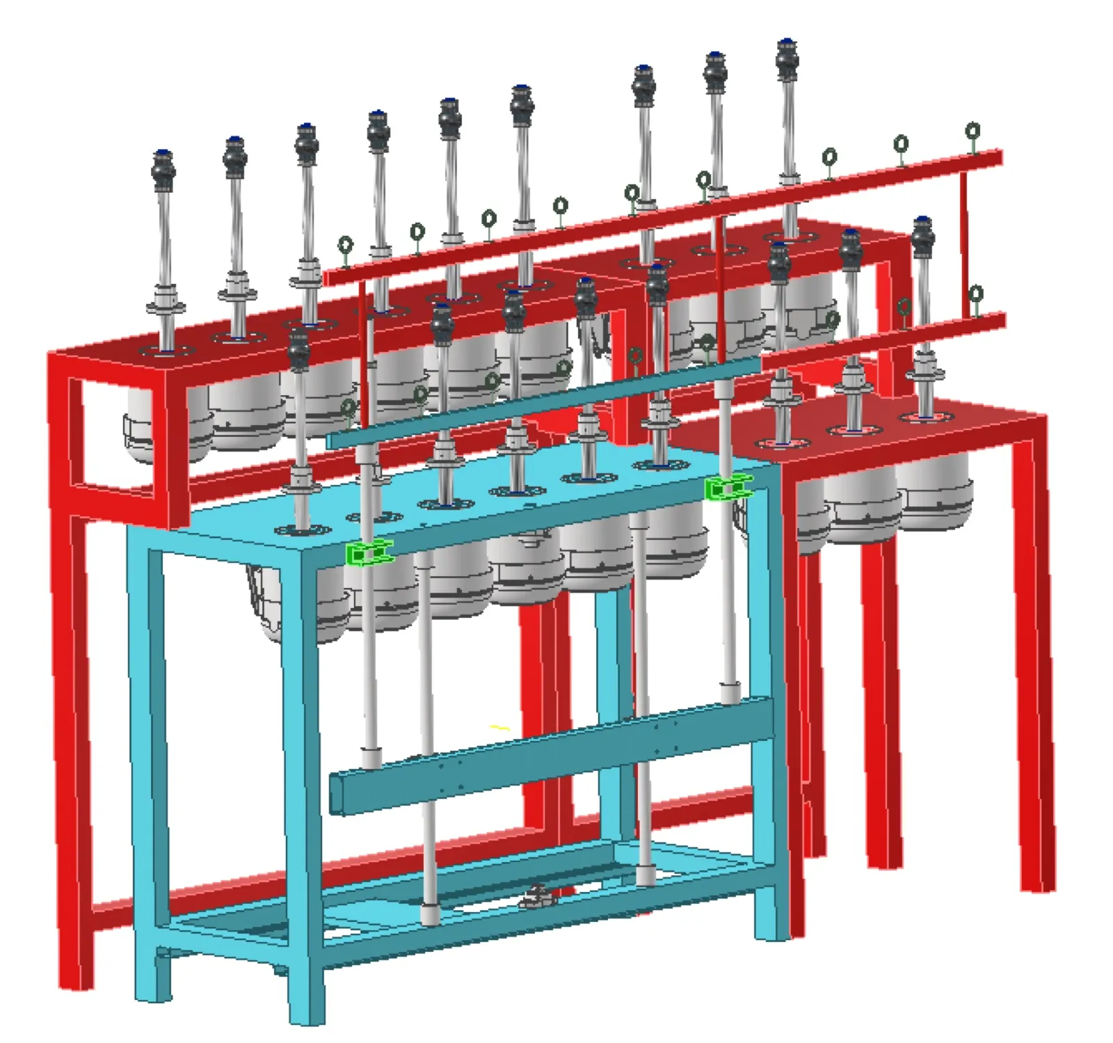
We chose a lateral expansion of the existing machine to 18 cones, with 6 new stations on each side of the original. Each station has an independent motor, as the client required: any adjustment, maintenance or stop at one station does not affect the others, which increases operating continuity. The shafts were designed to take both winding and waxing cones.
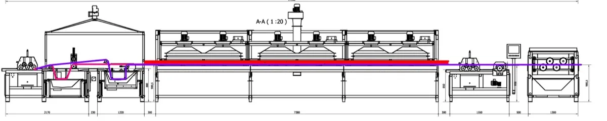
The plant layout was defined from a survey of the space: safe operator circulation, access to load and remove cones, and a thread path free of interference with other equipment.
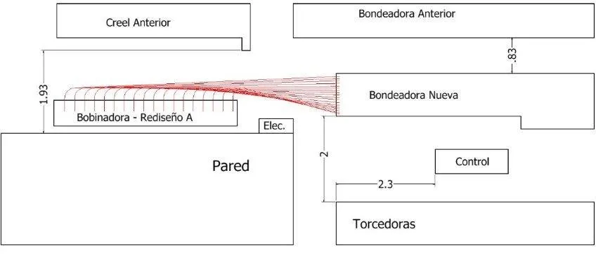 Plant layout: the redesigned bonding machine and its thread path within the available space.
The winder was split into three subsystems: frame and oscillation, built in full, and bobbin, whose parts are bought from the Italian manufacturer MP SRL.
Frame
The frame is a welded structure of 60 × 40 mm rectangular tube, 2 mm wall (20.8 m in total, nested into standard 6 m bars), with a 5 mm top plate waterjet-cut for motor mounting and cable routing, and 2 mm sheet covers cut and bent.
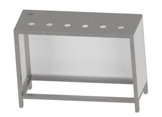 Frame of one of the side stations.
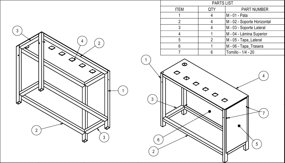 Frame assembly drawing and parts list.
I compared two material options: stainless steel with TIG welding, and carbon steel with powder coating. The estimated cost was COP 5.8 million versus 1.6 million, almost entirely due to the cover sheets. The recommendation was to make the covers in carbon or galvanized steel, since they are bolted on, and keep the better finish for the structure and the motor plate.
Oscillation
For the thread to cover the whole cone, a horizontal bar moves the threads up and down during winding. We reused the torque of the original motor, which proved sufficient to drive a longer bar, extended with two profiles joined by plates and M5 bolts to keep the system modular. This added 12 threads without a new drive and with synchronized motion.
To avoid vibrations that would affect winding uniformity, the bar is stabilized with linear bearings sliding on shafts welded to the auxiliary frames, with adjustment slots to absorb manufacturing and positioning tolerances. Threads are guided by ceramic thread guides at every change of direction: 18 at the machine inlet, 12 at the entrance of the original bonding machine and 6 before the cones.
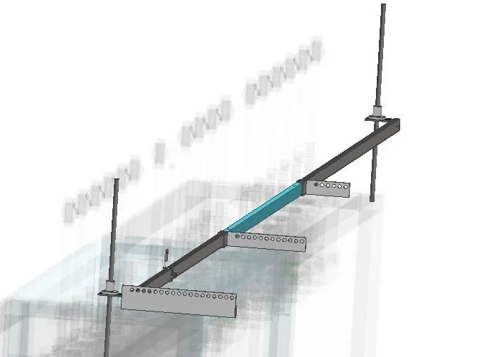 Oscillation subsystem, highlighted on the full assembly.
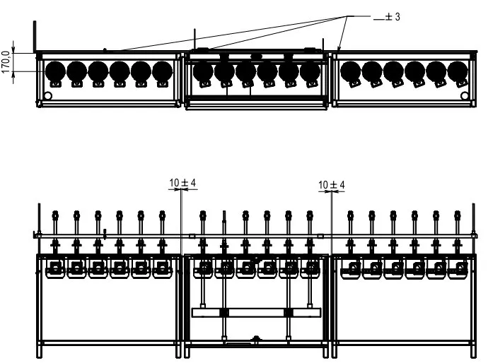 Assembly drawing: 1 cm gap between frames and collinearity for the linear bearing.
Bobbin
The bobbin subsystem couples each motor shaft with the winding accessories bought from MP SRL. The drawing defines the assembly between the shaft and its three accessories.
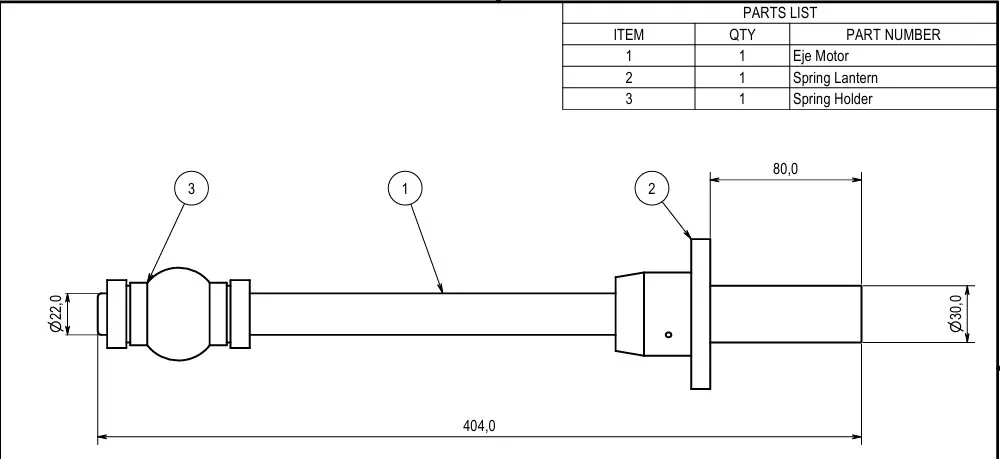 Bobbin assembly: motor shaft and winding accessories.
Manufactured deliverables
Besides the winder package, the team manufactured the line’s critical parts:
- Five types of technical guides, TIG-welded.
- 58 counterweight sensors, short and long, laser-cut, with their aluminum spacers.
- The new ceramic thread guide holder.
 One of the manufacturing drawings delivered.
Conclusions
- Detailed design for manufacturing. Delivering a machine for a third party to build demands complete shop drawings, justified tolerances, a traceable BOM and clear assembly sequences. It was the project where I went deepest into large-assembly CAD and technical documentation in Autodesk Inventor.
- Consulting rigor. Working with an industrial client meant surveying the process and the plant space, turning their needs into measurable requirements, presenting weekly progress and justifying every decision with calculations and costs.
- Industrial processes and machinery. I saw up close how a continuous textile line operates and worked with manufacturing processes such as TIG welding, laser and waterjet cutting, sheet bending and powder coating, and how each one shapes the design.
It’s part of the University chapter.